
Underfloor heating before screed pouring: what must be inspected before it disappears under the floor
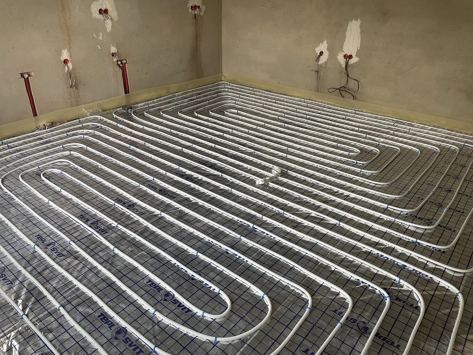
The moment just before pouring screed over the loops is the last chance to check the installation with the naked eye and a manometer. After concreting, a mounting error turns into floor cutting, and lack of a protocol – into a dispute about who will pay. This text shows what an engineer must inspect and sign off on, and what a contractor must do right the first time.
Why this is a disappearing inspection, not "eyeballing"
Disappearing inspection applies to work that will soon become inaccessible for inspection. Heating loops, manifold, expansion tape, and pipe fasteners meet this criterion literally – one day separates them from being buried under concrete or anhydrite. If no one signed a protocol before pouring and a leak appears three years later, it will be difficult to determine whether the pipe was damaged during rebar installation or the installation itself had a defect. In practice, this means a dispute between the heating contractor, the concrete crew, and the investor – with no document to settle it.
More than just the pipe disappears under the screed. The actual pipe routing, loop spacing, condition of the edge tape, how it crosses expansion joints, and the height at which pipes lie all vanish. After concreting, this can only be verified with a thermal imaging camera or by chipping out – both methods are approximate or destructive.
Therefore, the site inspector or construction manager should physically see the installation before pouring and confirm it with a signature – not based on a photo sent by the contractor, but through a site visit or, with distributed teams, a documented report with date and photos in a system like FixControl. Rule to remember: without a signed protocol of the tightness test and without photos of pipe routes, you do not authorize pouring. This is one decision that can only be reversed by chipping out.
Compliance with the installation design
Before the manifold disappears under the casing and the loops under the screed, compare what is on site with the working design. Three things to check first:
- Pipe spacing – should result from thermal calculations for the specific room, not from one template for the entire house. Spacing greater than 30 cm is treated as a design error.
- Circuit length – loops longer than 100–110 meters require checking hydraulic resistance and pump selection; in a typical single-family home, circuits typically fit in the range of 70–90 m, and values around 100 m and above 120 m require additional flow control checks, not accepting them as standard.
- Surface area per loop – a circuit serving more than approximately 32 m² with the longer side exceeding 8 m is another signal of design error.
Also check the zoning: the number of loops and their assignment to rooms must match the control system (thermostats, actuators on the manifold). If one loop serves two rooms with different settings, regulation will never work properly.
The last point is pipe passages through structural expansion joints and the connection point with the manifold – a pipe in the expansion zone must run in a protective sleeve, otherwise structural movement will cut it. If any of these points deviates from the design, you stop the inspection and report the non-compliance – do not sign the protocol "conditionally," counting on corrections afterward.
Tightness test before pouring – how to document it
The tightness test answers one question: are there visible leaks in the tested range. It does not confirm heating power, correct loop spacing, or proper flow rates – those are separate checks, described above.
There is no single universal pressure value and test time for every system. EN 1264-4:2021 (functioning in Poland also as BS EN 1264-4:2021) specifies that the test must be performed before covering the installation and how to document it – but the specific pressure, medium, and allowable drop always come from the system instructions of the given pipe and manifold manufacturer. In industry materials, a reference value of 1 MPa (10 bar) maintained for 24 hours appears, with an allowable drop to 0.02 MPa (0.2 bar) – this is a useful example procedure, but not a value to automatically copy into the protocol without checking the technical sheet of the specific system.
Practical sequence: establish the manufacturer and document that specifies test parameters; mark the tested loops and manifolds; fill and bleed each loop separately until an even stream of water flows from the return fitting; connect the pressure pump and manometer of known accuracy; build pressure gradually, not exceeding the parameters of the weakest element in the system; record time, pressure, and ambient temperature at at least three points (start, control, end); inspect all accessible connections – lack of pressure drop on the manometer alone does not replace visual inspection.
The tightness test protocol must contain: manufacturer and system type, tested range (which loops and manifolds), medium used, pressure and time according to system instructions, readings from at least three moments with temperature, visual inspection result, manometer model and accuracy, date, signatures of the contractor and – according to good inspection practice – the site manager or site inspector. Photos of the manometer with visible reading and loop description, taken with date in an application like FixControl, protect both sides in case of a dispute during the warranty period.
Common execution errors that only appear after screed pouring
- Pipe bend radius too small. For a 16 mm pipe, a radius less than 8 cm (below 5 times the diameter) risks micro-cracks or cross-section narrowing – the effect appears only as weaker flow or leaks after months of system operation.
- Mechanical damage from walking on loops or laying rebar. A pipe pierced by a rebar or crushed by a wheelbarrow full of concrete is the most expensive error on the list – repair means chipping out the screed.
- Missing or leaking expansion tape around room walls and at thresholds. Without it, the screed cracks in the first heating season because there is no room to accommodate thermal expansion.
- Loops fastened too sparsely to the mat or mesh. Pipes shift during concrete placement, change spacing, and may move closer to the surface than the design assumed.
Preventing each of these errors comes down to the same thing: fasten according to the system (clamps every 50–80 cm on straight sections and every 30 cm on curves), protect installed loops from heavy equipment and unnecessary foot traffic, and perform the tightness test before anyone starts laying rebar or bringing in the concrete pump. If the test is successful before rebar installation and you do not repeat it in full scope afterward – leave the installation under pressure during rebar and concrete work so that any drop is visible immediately, not after the fact.
Insulation, rebar, and screed thickness above the pipe
Screed layer height is calculated from the formula hpos = 45 + dzewr + 2 [mm], where dzewr is the outer diameter of the pipe. For a typical 16 mm pipe, this gives approximately 63 mm total screed height above insulation – the minimum value, not a target thickness to round down.
Thermal insulation under loops must have a thermal resistance suited to room location: R = 0.75 m²K/W above a heated room, R = 1.25 m²K/W above an unheated room or on ground at soil temperature Tz ≥ 0°C, and R = 2.00 m²K/W on ground at Tz between −5°C to −15°C. Insulation that is too thin cannot be corrected after pouring – it is an irreversible error without chipping out the entire floor.
Before pouring, check with a laser or level the actual pipe height at several points in each room, especially at densified areas in edge zones and at transitions. If the pipe lies higher in any spot than the assumed coverage thickness, decide before pouring whether to weight it down to level or adjust screed thickness in that spot – do not leave this to the concrete crew's judgment.
Inspection checklist and documentation in FixControl
Before authorizing pouring, collect in one place:
- Photo of the manifold with legible loop designations (number, room, length).
- Photos of all loop routing, taken so their position can be reproduced on the floor plan.
- Tightness test protocol signed by the contractor and the inspecting person, plus a photo of the manometer with the result.
- Confirmation of spacing, length, and zoning compliance with the design.
- Photos of expansion tape around the perimeter and where it crosses structural expansion joints.
- Measurement of pipe height with a laser or level at critical points.
If something does not comply with the design – e.g., spacing exceeds assumptions or expansion tape is missing on a wall section – a defect report should contain: exact location (room, loop, distance from reference point), photo with measurement, description of non-compliance in relation to a specific design provision, person responsible for correction, and deadline. Recording this in FixControl with date and photo provides hard evidence of when the defect arose and whether it was fixed before pouring – not at final inspection when no one remembers the details.
Documentation made at this stage is the only material to rely on if a claim appears after the heating season. A photo with loop number and measurement takes five minutes – chipping out the floor takes weeks and a dispute over who is at fault.
Sources
- Projekt Ogrzewania: Próba szczelności ogrzewania podłogowego. — https://projekt-ogrzewania.pl/proba-szczelnosci-ogrzewania-podlogowego/
- Ogrzewnictwo.pl: Jak wykonać próbę szczelności w instalacji wodnego ogrzewania podłogowego? — https://www.ogrzewnictwo.pl/artykuly/ogrzewanie-plaszczyznowe/jak-wykonac-probe-szczelnosci-w-instalacji-wodnego-ogrzewania-podlogowego
- Ogrzewnictwo.pl: Wytyczne projektowe i wykonawcze dla ogrzewania podłogowego — https://www.ogrzewnictwo.pl/artykuly/ogrzewanie-plaszczyznowe/ogrzewanie-scienne-i-sufitowe/wytyczne-projektowe-i-wykonawcze-dla-ogrzewania-podlogowego
- Projekt Ogrzewania: Jak zaplanować rozmieszczenie pętli grzewczych w ogrzewaniu podłogowym? — https://projekt-ogrzewania.pl/jak-zaplanowac-rozmieszczenie-petli-grzewczych-w-ogrzewaniu-podlogowym/
- Przeciek24.com – Świat Instalacji: Próba Szczelności Ogrzewania Podłogowego — https://przeciek24.com/proba-szczelnosci-ogrzewania-podlogowego/
- Instalator24: Najczęściej błędy przy montażu ogrzewania podłogowego — https://instalator24.pl/pl/blog/najczestsze-bledy-przy-montazu-ogrzewania-podlogowego-1751609458.html
See also
- Screed curing with underfloor heating: procedure and inspection protocol
- Construction moisture in a new house: how to ventilate in fall and winter to prevent mold
- Anhydrite and cement screeds in fall: when to measure moisture and how to do CM measurement without errors
Photo: Viii23dawari / Wikimedia Commons / CC BY-SA 4.0
